
Routing components are the foundation of any SOLIDWORKS Electrical 3D design. They define the exact locations where wires, cables, or harnesses begin and end on real-world, manufacturer-specific components. Properly defining routing points on connectors ensures that SOLIDWORKS Electrical can create accurate and physically realistic routes, helping maintain design accuracy and consistency throughout the 3D design process
In this walkthrough, we’ll take a standard circular connector and turn it into a fully routable component by creating routing points (C-Points) directly from a manufacturer part reference step by step, using the Routing Library Manager.
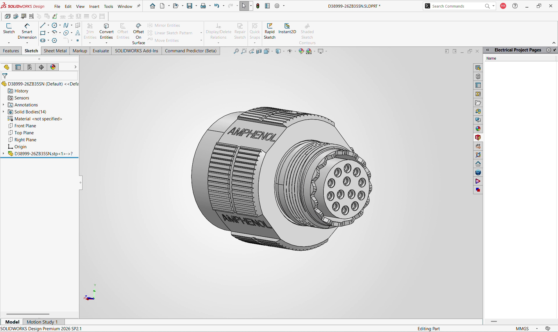
1. Open the 3D Part
Begin by opening the 3D component you want to route. In this example, we are using an Amphenol D38999-26ZB35SN circular connector.
At this stage, the Feature Manager design tree contains only the default reference planes, Origin, and the imported part body. No routing sketches or connection points have been created yet, providing a clean starting point for defining the routing geometry.
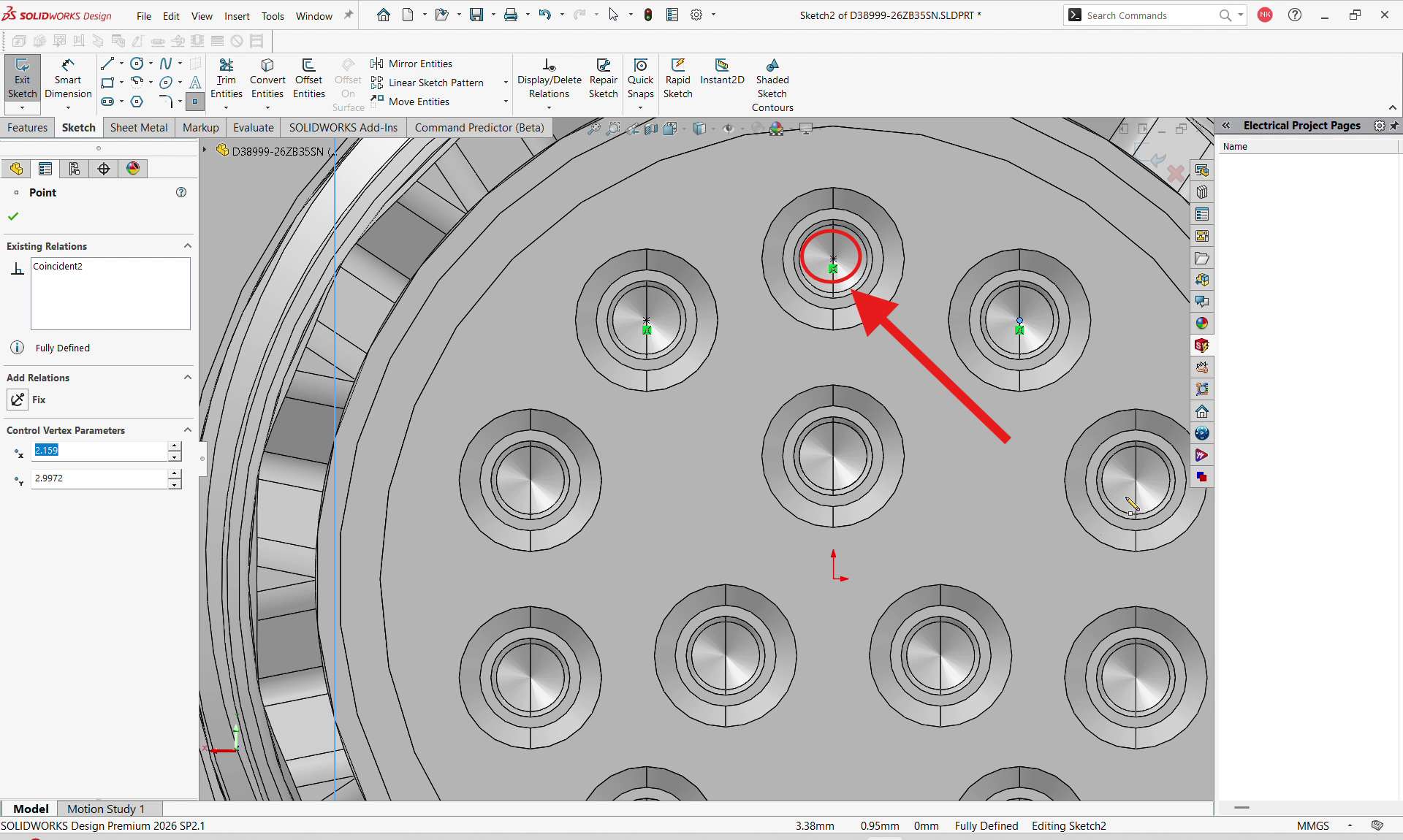
2. Create a Point Reference for the Routing
Next, create a sketch point on the component at each location where a routing connection needs to begin. For a multi-pin connector, place each sketch point at the center of the corresponding pin face to ensure the routing originates from the correct location.
Use a Coincident relation to position the point precisely on the required geometry, and apply a Fix relation to fully define and maintain its position.
If the component requires any preparation before creating the routing points such as additional reference planes, sketches, or other CAD operations, complete these steps first. This ensures that each sketch point is positioned accurately and provides a reliable starting location for the routing path
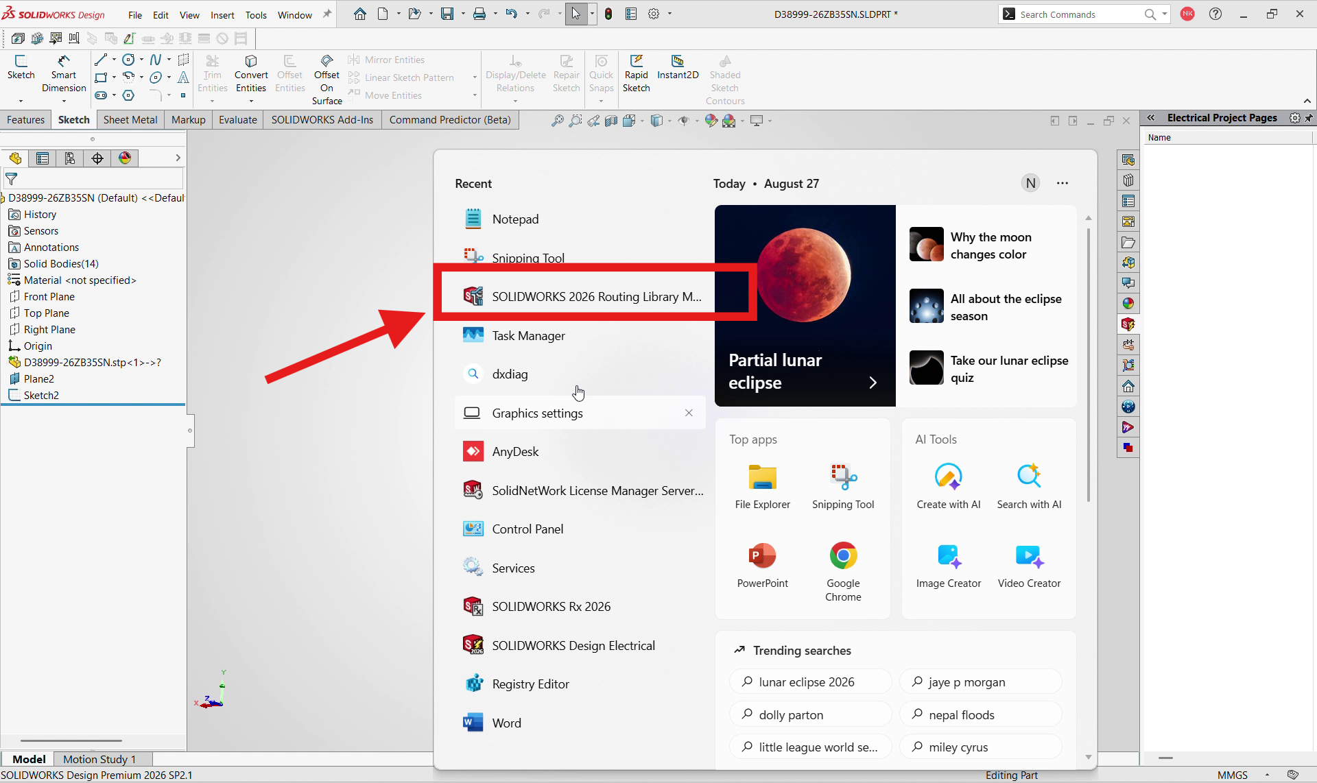
3. Open the Routing Library Manager
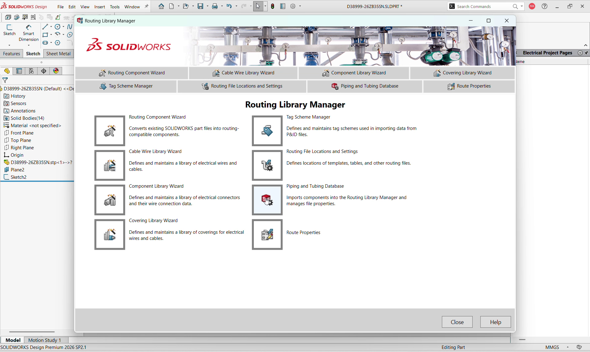
With the sketch points in place, open the Routing Library Manager. You can launch it directly from the Windows search bar.
The Routing Library Manager is the central hub for routing-related settings in SOLIDWORKS Electrical. It provides access to component wizards, cable and wire libraries, tag schemes, and routing file settings, allowing you to manage the resources required for your 3D routing workflow.
4. The Routing Library Manager
The Routing Library Manager provides access to all the essential routing tools from a single interface. From here, you can access the Routing Component Wizard, Cable Wire Library Wizard, Component Library Wizard, Covering Library Wizard, Tag Scheme Manager, Routing File Locations and Settings, Piping and Tubing Database, and Route Properties.
Having these tools in one place makes it easier to configure, manage, and maintain the libraries and settings required for an efficient SOLIDWORKS Electrical 3D routing workflow.
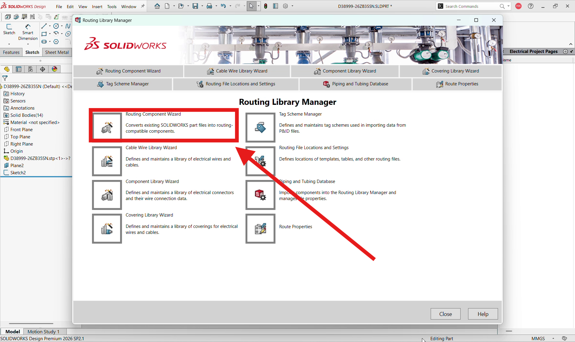
5. Launch the Routing Component Wizard
From this screen, select Routing Component Wizard. This converts your existing SOLIDWORKS part file into a routing-compatible component.
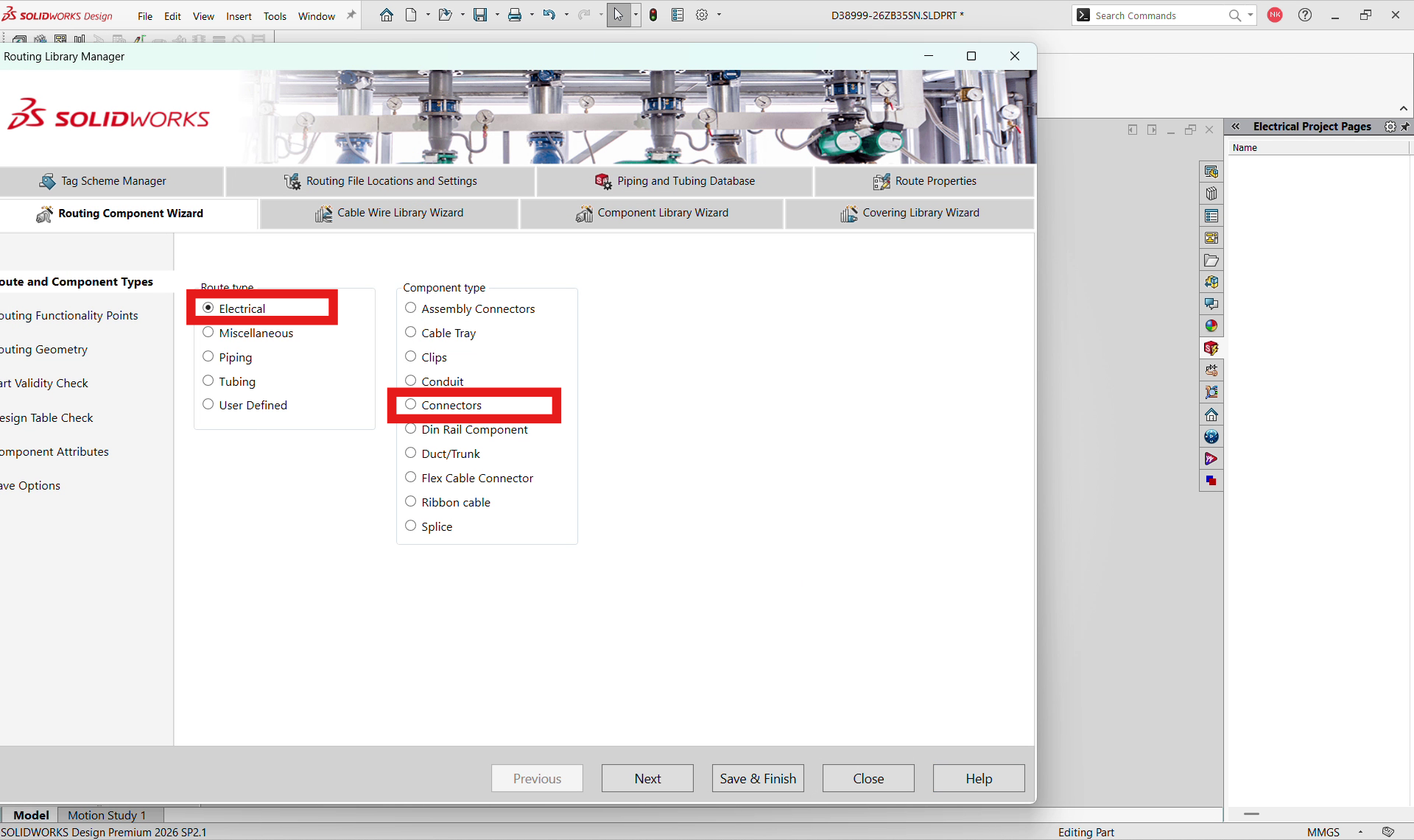
6. Choose Electrical and Connectors
On the Route and Component Types page, set Route type to Electrical then choose the Component type that matches your part, in this case, Connectors > and click Next.
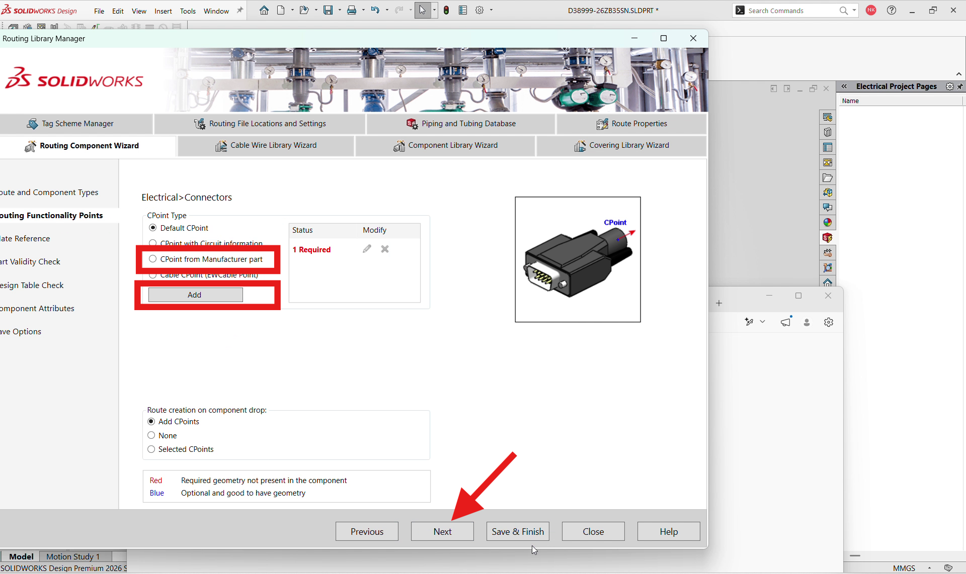
7. Select CPoint from Manufacturer Part
The Electrical > Connectors page opens next. Under CPoint Type, select CPoint from Manufacturer part, then click Add. Once added, move on to Next if your component requires mate references- in my case I don’t need the mate reference
8. Pick the Manufacturer Part from the Library
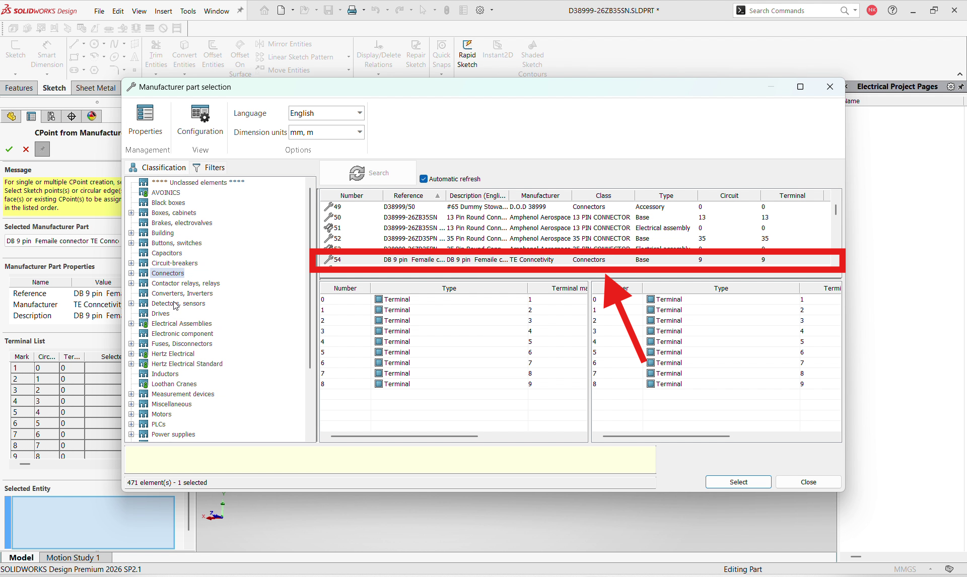
Clicking Add opens the Manufacturer Part Selection dialog. Browse the Classification tree to the Connectors category, then select the exact part from the list on the right. Here, the DB 9 pin Female connector from TE Connectivity, with 9 circuits and 9 terminals. The terminal tables below confirm the pin-to-terminal mapping before you commit to the part
9. Browse and Confirm the Selected Part
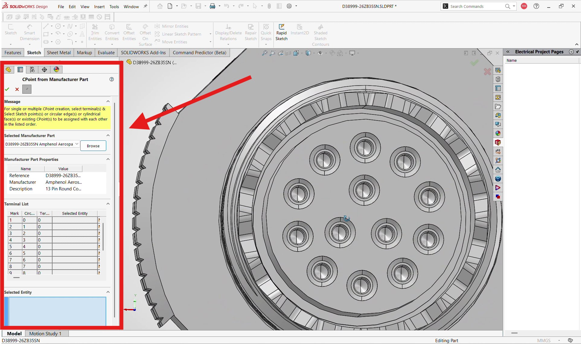
Back in the CPoint from Manufacturer Part panel, your selected part now appears under Selected Manufacturer Part, along with its Reference, Manufacturer, and Description. The Terminal List shows every terminal waiting to be matched to a point on your 3D geometry , this is where you’ll go pin by pin on the connector face shown in the graphics area
10. Assign Sketch Points to Each Terminal
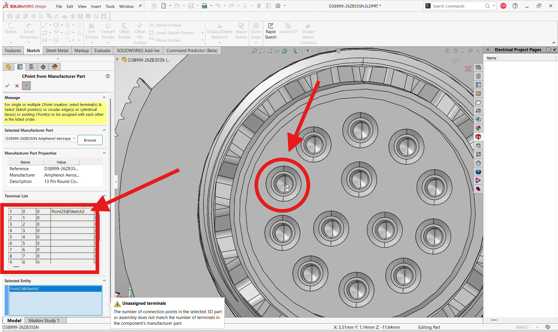
Select each sketch point on the connector face in the same order as the terminals are defined. As you select each point, SOLIDWORKS adds it to the Terminal List with its corresponding name, such as Point25@Sketch2, and associates it with the appropriate terminal mark. If the number of selected points does not match the number of terminals defined for the manufacturer part, SOLIDWORKS displays an “Unassigned terminals” warning clearly indicating that additional pins still need to be assigned.
Benefit: You get a fully traceable, terminal-accurate mapping between your 3D geometry and the manufacturer’s pinout, which is exactly what later routing and validation depend on.
11. Confirm the C-Points and Save
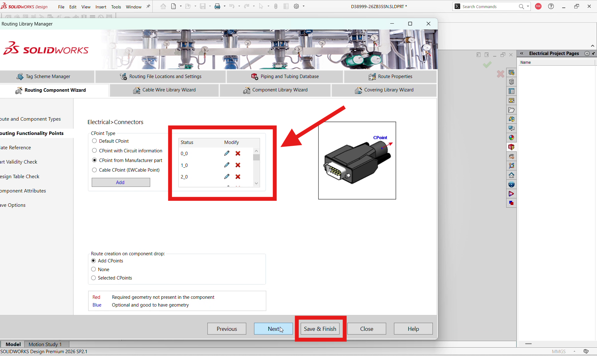
Once every terminal has a matching point, the Status list updates to show each C-Point created — 0_0, 1_0, 2_0, and so on — confirming the connection points now exist on your part. From here, click Next and then Save & Finish to commit the routing component.
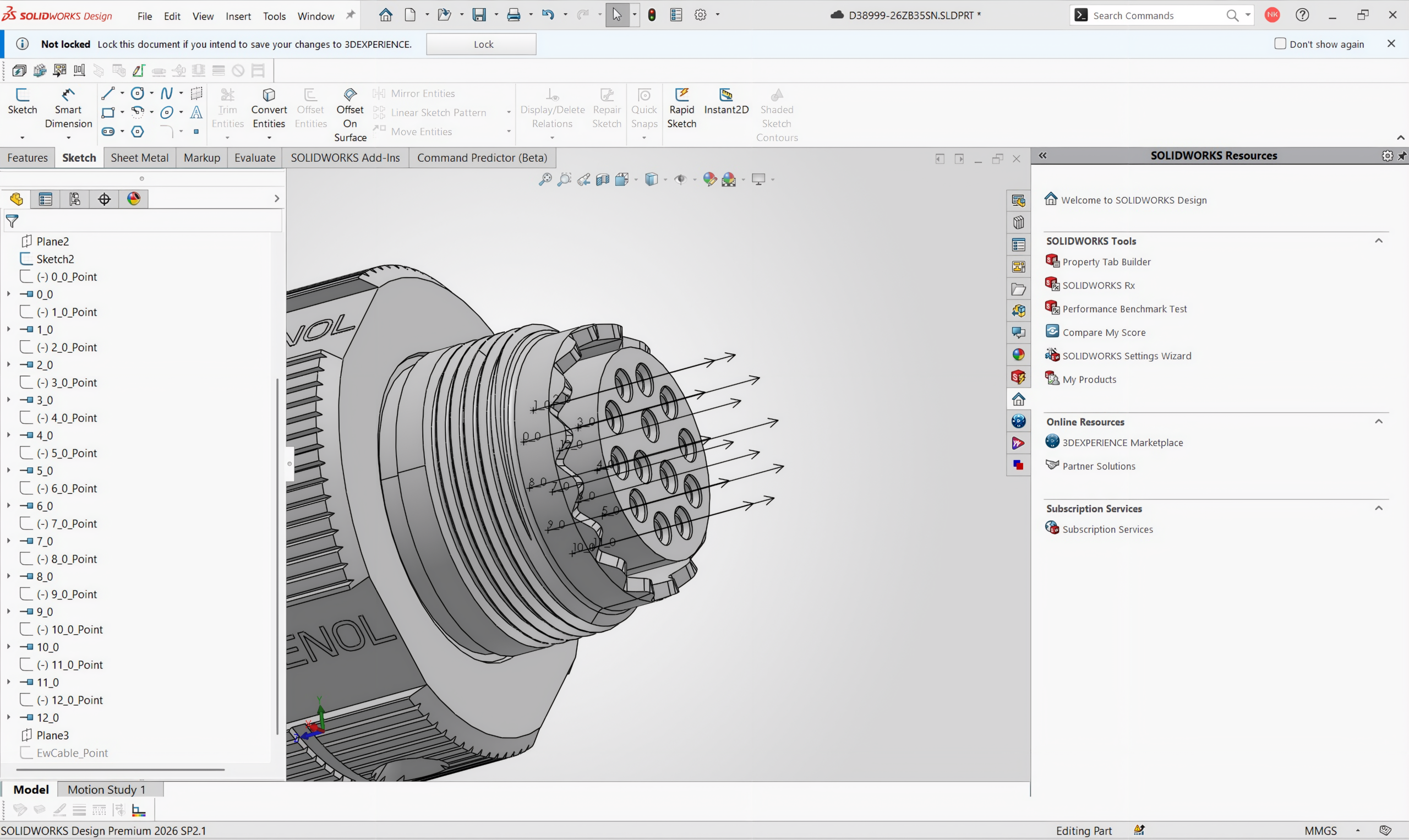
12. The Finished Routing-Ready Component
Back in the model, the feature tree now lists a full set of created points — 0_0_Point through 12_0_Point — one for every pin on the connector. On the 3D part itself, each C-Point is labeled directly on the face it belongs to, so the component is now fully ready to drop into an assembly and route
Wrapping Up
That’s the complete flow for creating routing points on a SOLIDWORKS Electrical 3D component using a manufacturer part reference — from the first sketch point to a fully rendered, terminal-matched set of C-Points. Once your library part carries its own routing points, every future assembly that uses it inherits accurate, ready-to-route connections automatically
Contributor: Naveen Kumar Ravi, Elite Application Engineer specializing in SOLIDWORKS, with 10 years of experience helping engineering teams maximize SOLIDWORKS Electrical through technical expertise and innovation.
Shape the future of design with smarter solutions today!
